

Anritsu MW8208A PIM Master Passive Intermodulation Analyzer w/ OPT: 0425
$2,029.00
Availability:
In stock
SKU
6C128
Condition: Refurbished / Calibrated
Warranty: 1 YEAR WARRANTY
Anritsu MW8208A PIM Master
PIM Master™ Introduction
Anritsu Company introduces its first generation high performance PIM testing solution for the Cellular, E-GSM, PCS, and AWS, frequency bands. Anritsu has developed the PIM Master to verify if receiver interference at a cell site is due to an intermodulation product of two or more transmit frequencies, also known as passive intermodulation (PIM).
The PIM Master generates two high power tones in the transmit band of a base station and Anritsu’s family of handheld RF instruments’ PIM Analyzer measures the 3rd, 5th, or 7th order intermodulation products in the receive band coming back down the same cable. And the GPS option will record the location of the measurement.
Anritsu’s handheld instruments supporting the PIM Master include:
The current standard of PIM testing offers a well-known system of two primary carriers and a calculated PIM frequency, which is monitored via a spectrum analyzer. This provides a measurement of the overall linearity of the antenna system and the surrounding environment.
As more power goes up the antenna lines a coaxial connection is more likely to cause a fault on a tower. Traffic through the site plays a big part – a relatively quiet site will not usually see the same performance problems that a busy site will see. The main reason we use a PIM test is that it is the most comprehensive measure of electrical connection quality that is commercially available.
PIM Testing versus Line Sweeping
A PIM test cannot, however, measure VSWR. This means the test set will not see an open or short condition, unless the fault displays non-linear behavior. A return loss figure that is failing will not be determined with a PIM test measurement.
Components deteriorate as they age due to a number of issues, including poor mechanical design, poor installation, and moisture ingress (which is the most significant). On-site faults can mostly be categorized into two main types: linearity related and impedance related.
PIM testing measurements reflect the overall linearity of an antenna feed line and Line Sweep measurements reflect the overall impedance matching of all of the components in an antenna feed line. Both tests need to be performed to ensure the overall quality of an antenna feed line. Passing one type of test (PIM or Line Sweep) does not guarantee the other test will pass.
Symptoms of PIM problems
Many symptoms could be indicators of PIM problems. These include:
Where is the PIM?
Anritsu labs has invented and succeeded in developing a patented technology that pinpoints PIM faults called Distance-to-PIM (DTP)™. No more wasting time rappelling down towers trying to locate PIM, no more wondering if the PIM is coming from the antenna system or the surrounding environment.
The Distance-to-PIM test is simple, immediate, and accurate. DTP informs the technician of the distance and relative magnitude of all the PIM sources simultaneously, both inside the antenna system and beyond the antenna. DTP is similar to Distance-to-Fault (DTF), which Anritsu introduced in the Site Master™ in 1997, displaying distance versus impedance changes. DTP utilizes algorithms much like DTF to show distance versus the magnitude of non-linear faults. DTP is a standard feature included with the PIM Master.
Distance-to-PIM lab results
DTP shows the location for PIM problems within the antenna system, as well as distance to external PIM sources outside the antenna system. The DTP example to the left identified the roof obstruction at Marker 4 at 34.4 m. Markers 1, 2, and 3 correctly identified other PIM sources in the cable. This is an incredible step forward in improving the quality of information received from the on-site PIM test.
The Distance-to-PIM test offers far more insight than traditional PIM testing. This information can speed up repairs, control repair costs, and help plan budgets accurately. Comparison of PIM values over time can show if a device is deteriorating with age. This permits fault correction before a failure causes dropped or blocked calls.
2 x 40 Watt PIM Testing
PIM problems can be intermittent and power sensitive. This is often the case when PIM problems are just beginning to show up. This can be due to light corrosion, high traffic loading, or changing weather conditions activating environmental diodes. Using higher power levels can often force otherwise intermittent failures to become visible. Higher power levels may be required to find faults in a multicarrier antenna system and to discover microscopic arcing in connectors. In many cases PIM faults cannot be discovered with just 2 x 20 Watts of power. With the ability to test at 40 Watts, one can spot serious problems that cannot be seen on a 20 Watt PIM tester
Storing and Recalling Setups and Measurements
When saving files many choices are available. One can save and recall:
Run Line Sweep Tests on the same instruments
Since both PIM measurements and Line Sweep measurements can be made on the same instruments (Site, Cell, or BTS Masters) one can efficiently make Line Sweep measurements at the same time. Now all PIM measurements and Line Sweep measurements are stored together on the same instrument. An installation contractor or technician only has to learn how to use one instrument to make all related antenna measurements for linearity and impedance testing.
Line Sweep Tools for Cable, Antenna, and PIM Analysis
Anritsu’s Line Sweep Tools is a new generation post processing tool to manage, archive and report on all cable, antenna, and PIM analyzer sweeps. In one tool all measurements can be incorporated into one unified report per antenna system. Now in one integrated report an operator can have all of the information on the integrity of an antenna system with the measurements of:
PIM Master™ Certified PIM Measurement Training Course
pecialized PIM Master™ passive intermodulation measurement training is an intense one-day instructor led training course that focuses on making PIM measurements (theory and lab). This is modeled on our successful Site Master™ Certified Line Sweep course.
Customer Support
Like all Anritsu products, the PIM Master has a range of support products, services and training allowing you to maximize your returnon-investment.
What is PIM?
PIM is a form of intermodulation distortion that occurs in passive components normally thought of as linear, such as filters, combiners, surge protectors, cables, connectors, and antennas. However, when subject to the high RF powers found in cellular systems, these devices can generate spurious signals. PIM shows up as a set of unwanted signals created by the mixing of two or more strong RF signals in a non-linear device, such as in a loose or corroded connector, or in nearby rust. Other names for PIM include the “diode effect” and the “rusty bolt effect.” This pair of formulas can predict PIM frequencies for two carriers:
IMn+m = nF1 – mF2
IMn+m = nF2 – mF1
F1 and F2 are the Tx carrier frequencies and the constants n and m are positive integers. When referring to PIM products, the sum of n + m is called the product order, so if m is 2 and n is 1, the result (2+1=3) is referred to as a third order product or IM3.
Typically, the third order product is the strongest causing the most harm when they fall into the Rx band. Because PIM amplitude becomes lower as the order increases, higher order products typically are not strong enough to cause direct frequency problems, but they usually assist in raising the adjacent noise floor. Once this raised noise floor crosses into the Rx band, it then has an open door (and sometimes gain via an LNA) into the BTS. It is important to recognize that intermodulation created from modulated signals occupies more bandwidth than the fundamentals. PIM products can be very wide band, covering wide swaths of frequencies.
Why has PIM become an issue recently?
devices has increased the network traffic within a cellular system to the degree that it is greatly affecting network performance. As extra cellular transmitters and modulation formats are commissioned into service in new or existing sites, the statistical performance can appear to change dramatically. Ultimately, this can result in poor site/sector performance and reduced coverage, and this is why testing for PIM is now required in the field.
PIM has come to the forefront of network problems recently due to a variety of reasons which can be any combination of the following:
Specifications:
For full Anritsu MW8208A product specifications, please click here: Anritsu MW8208A
PIM Master™ Introduction
Anritsu Company introduces its first generation high performance PIM testing solution for the Cellular, E-GSM, PCS, and AWS, frequency bands. Anritsu has developed the PIM Master to verify if receiver interference at a cell site is due to an intermodulation product of two or more transmit frequencies, also known as passive intermodulation (PIM).
The PIM Master generates two high power tones in the transmit band of a base station and Anritsu’s family of handheld RF instruments’ PIM Analyzer measures the 3rd, 5th, or 7th order intermodulation products in the receive band coming back down the same cable. And the GPS option will record the location of the measurement.
Anritsu’s handheld instruments supporting the PIM Master include:
- Site Master™ S332E, S362E
- Spectrum Master™ MS271xE, MS2721B, MS272xC
- Cell Master™ MT8212E, MT8213E
- BTS Master™ MT8221B, MT8222B
The current standard of PIM testing offers a well-known system of two primary carriers and a calculated PIM frequency, which is monitored via a spectrum analyzer. This provides a measurement of the overall linearity of the antenna system and the surrounding environment.
As more power goes up the antenna lines a coaxial connection is more likely to cause a fault on a tower. Traffic through the site plays a big part – a relatively quiet site will not usually see the same performance problems that a busy site will see. The main reason we use a PIM test is that it is the most comprehensive measure of electrical connection quality that is commercially available.
PIM Testing versus Line Sweeping
A PIM test cannot, however, measure VSWR. This means the test set will not see an open or short condition, unless the fault displays non-linear behavior. A return loss figure that is failing will not be determined with a PIM test measurement.
Components deteriorate as they age due to a number of issues, including poor mechanical design, poor installation, and moisture ingress (which is the most significant). On-site faults can mostly be categorized into two main types: linearity related and impedance related.
PIM testing measurements reflect the overall linearity of an antenna feed line and Line Sweep measurements reflect the overall impedance matching of all of the components in an antenna feed line. Both tests need to be performed to ensure the overall quality of an antenna feed line. Passing one type of test (PIM or Line Sweep) does not guarantee the other test will pass.
Symptoms of PIM problems
Many symptoms could be indicators of PIM problems. These include:
- Receiver desensitization (raised noise floor)
- Rx Diversity alarms
- Spectral re-growth in the transmitter mask
- Excessive dropped/blocked calls
- Cell site coverage shrinking
- Complaints of interference from neighboring cell site owners
Where is the PIM?
Anritsu labs has invented and succeeded in developing a patented technology that pinpoints PIM faults called Distance-to-PIM (DTP)™. No more wasting time rappelling down towers trying to locate PIM, no more wondering if the PIM is coming from the antenna system or the surrounding environment.
The Distance-to-PIM test is simple, immediate, and accurate. DTP informs the technician of the distance and relative magnitude of all the PIM sources simultaneously, both inside the antenna system and beyond the antenna. DTP is similar to Distance-to-Fault (DTF), which Anritsu introduced in the Site Master™ in 1997, displaying distance versus impedance changes. DTP utilizes algorithms much like DTF to show distance versus the magnitude of non-linear faults. DTP is a standard feature included with the PIM Master.
Distance-to-PIM lab results
DTP shows the location for PIM problems within the antenna system, as well as distance to external PIM sources outside the antenna system. The DTP example to the left identified the roof obstruction at Marker 4 at 34.4 m. Markers 1, 2, and 3 correctly identified other PIM sources in the cable. This is an incredible step forward in improving the quality of information received from the on-site PIM test.
The Distance-to-PIM test offers far more insight than traditional PIM testing. This information can speed up repairs, control repair costs, and help plan budgets accurately. Comparison of PIM values over time can show if a device is deteriorating with age. This permits fault correction before a failure causes dropped or blocked calls.
2 x 40 Watt PIM Testing
PIM problems can be intermittent and power sensitive. This is often the case when PIM problems are just beginning to show up. This can be due to light corrosion, high traffic loading, or changing weather conditions activating environmental diodes. Using higher power levels can often force otherwise intermittent failures to become visible. Higher power levels may be required to find faults in a multicarrier antenna system and to discover microscopic arcing in connectors. In many cases PIM faults cannot be discovered with just 2 x 20 Watts of power. With the ability to test at 40 Watts, one can spot serious problems that cannot be seen on a 20 Watt PIM tester
Storing and Recalling Setups and Measurements
When saving files many choices are available. One can save and recall:
- Set-up file
- Measurement file
- Jpeg screen shot (save only)
Run Line Sweep Tests on the same instruments
Since both PIM measurements and Line Sweep measurements can be made on the same instruments (Site, Cell, or BTS Masters) one can efficiently make Line Sweep measurements at the same time. Now all PIM measurements and Line Sweep measurements are stored together on the same instrument. An installation contractor or technician only has to learn how to use one instrument to make all related antenna measurements for linearity and impedance testing.
Line Sweep Tools for Cable, Antenna, and PIM Analysis
Anritsu’s Line Sweep Tools is a new generation post processing tool to manage, archive and report on all cable, antenna, and PIM analyzer sweeps. In one tool all measurements can be incorporated into one unified report per antenna system. Now in one integrated report an operator can have all of the information on the integrity of an antenna system with the measurements of:
- PIM
- Return Loss
- Insertion Loss
- Distance-to-Fault
PIM Master™ Certified PIM Measurement Training Course
pecialized PIM Master™ passive intermodulation measurement training is an intense one-day instructor led training course that focuses on making PIM measurements (theory and lab). This is modeled on our successful Site Master™ Certified Line Sweep course.
- Brief Course Outline
- Definition and Description
- How PIM differs from Return Loss
- Why is PIM a problem
- What causes PIM
- How to test for PIM
- PIM test equipment
- IM testing process
- Hints for successful testing
- Assessing Results
- Labs
- Hooking up the equipment and confirming proper operation
- Measuring known good and bad devices
- Device measurement practice
- Exams
- Theory and safety
- Hands-on practical
- Certification (after passing exams)
- Certificate of Completion
- Wallet-sized photo ID
Customer Support
Like all Anritsu products, the PIM Master has a range of support products, services and training allowing you to maximize your returnon-investment.
- Anritsu Line Sweep Tool for report generation
- A full line of PIM testing accessories
- Extended warranty
- PIM Certified Technician Training Course
- Made in the USA
What is PIM?
PIM is a form of intermodulation distortion that occurs in passive components normally thought of as linear, such as filters, combiners, surge protectors, cables, connectors, and antennas. However, when subject to the high RF powers found in cellular systems, these devices can generate spurious signals. PIM shows up as a set of unwanted signals created by the mixing of two or more strong RF signals in a non-linear device, such as in a loose or corroded connector, or in nearby rust. Other names for PIM include the “diode effect” and the “rusty bolt effect.” This pair of formulas can predict PIM frequencies for two carriers:
IMn+m = nF1 – mF2
IMn+m = nF2 – mF1
F1 and F2 are the Tx carrier frequencies and the constants n and m are positive integers. When referring to PIM products, the sum of n + m is called the product order, so if m is 2 and n is 1, the result (2+1=3) is referred to as a third order product or IM3.
Typically, the third order product is the strongest causing the most harm when they fall into the Rx band. Because PIM amplitude becomes lower as the order increases, higher order products typically are not strong enough to cause direct frequency problems, but they usually assist in raising the adjacent noise floor. Once this raised noise floor crosses into the Rx band, it then has an open door (and sometimes gain via an LNA) into the BTS. It is important to recognize that intermodulation created from modulated signals occupies more bandwidth than the fundamentals. PIM products can be very wide band, covering wide swaths of frequencies.
Why has PIM become an issue recently?
devices has increased the network traffic within a cellular system to the degree that it is greatly affecting network performance. As extra cellular transmitters and modulation formats are commissioned into service in new or existing sites, the statistical performance can appear to change dramatically. Ultimately, this can result in poor site/sector performance and reduced coverage, and this is why testing for PIM is now required in the field.
PIM has come to the forefront of network problems recently due to a variety of reasons which can be any combination of the following:
- Higher RF power
- Multiband systems on the same antenna lines
- Fully loaded multicarrier systems
- High density/traffic sites – heavily loaded
- Wideband receive filters
- Duplex antenna lines
- Wider bandwidth signals up to 5, 10, and 20 MHz
- Aging infrastructure – primarily connectors corroding and loosening
- Environmental diodes created by corrosion in the surrounding area
- Intermittent environmental diodes due to wet and dry conditions
- Neighboring cell sites generating PIM
Specifications:
| General Specifications | |
| Measurements | |
| PIM | 3rd, 5th, and 7th order intermodulation product in receive band (user selectable) |
| Noise Floor | Rx noise floor of base station |
| Distance-to-PIM | Distance and magnitude of multiple PIM sources |
| Instrument Setup Parameters | |
| Instruments Supported | Site Master™ S3x2E, Spectrum Master™ MS271xE, MS2721B, MA272XC Cell Master™ MT821xE, BTS Master™ MT8221B or MT8222B |
| Frequency | Carrier F1, Carrier F2, Intermod Order (3rd, 5th, 7th), Span |
| Amplitude | Ref Value, Scale, Ref Level Offset, Auto Range (On/Off), Amplitude Tone (On/Off) |
| Setup | Output Power, Test Duration (1 to 60 s), Normal ? A, Max Hold ? A, Display Type (Trace, Bar) |
| Parameter Setup | F1, F2, Power |
| Limit Lines | Limit (Upper/Lower), On/Off, Limit Move, Limit Alarm (On/Off) |
| GPS | On/Off, 3.3/5.0 V |
| DTP | Cable Velocity, Distance, Calibrate |
| Measurements | PIM Test (Measure/Off) Measure Noise Floor, Save Measurement |
| PIM Measurement Ranges | |
| RF Test Power | Two CW tones of 20, 30, or 40 Watts (≈ 43, 45, 46 dBm) (user selectable) |
| Transmit Frequency Range | MW8208A – 869 to 894 MHz |
| 3rd, 5th, and 7th Order Frequency Ranges | MW8208A – 824 to 849 MHz |
| Residual PIM Performance | < −112 dBm/−155 dBc typica |
| Measurable PIM order | 3rd, 5th, and 7th order intermodulation product (if in band) |
| Distance-to-PIM | Distance and magnitude of multiple PIM sources |
| PIM Master Connectors | |
| Test Port | 7/16 DIN, female, 50 Ω |
| RF Out | Type N, female, 50 Ω (connect to RF In on instrument) |
| 10 MHz Out | BNC, female, 50 Ω, 10 MHz (connect to Ext. Ref. In on instrument) |
| USB Interface | Type B (connect to USB Type A port on instrument) |
| AC Power | IEC60320 C14 |
| Power | |
| Emergency Stop | Red push button |
| AC Power | 90-240 VAC, 50/60 Hz |
| Electromagnetic Compatibility | |
| European Union | CE Mark, EMC Directive 2004/108/EC |
| Australia and New Zealand | C-tick N274 |
| Interference | EN 61326-1:2006 |
| Emissions | EN 55011:2007 |
| Immunity | EN 61000-4-2/-3/-4-4/-4-5/-4-6/-4-11 |
| Safety | |
| Safety Class | 2006/95/EC, EN 61010-1 Class 1 |
| Product Safety | IEC 60950-1 when used with Company supplied Power cablw |
| Environmental | |
| Operating Temperature − | −10 °C to 55 °C |
| Maximum Humidity | 95% |
| Shock | MIL-PRF-28800F Class 2 |
| Storage | −51 °C to 71 °C |
| Altitude | 4600 meters, operating and non-operating |
| Size and Weight | |
| Size | 300 mm x 425 mm x 500 mm (12 in x 17 in x 20 in) |
| Weight | 27 kg (59 lbs) |
For full Anritsu MW8208A product specifications, please click here: Anritsu MW8208A
Anritsu PIM Master MW8208A Passive Intermodulation Analyzer w/ Option 0425
The Following Anritsu Instruments Support The PIM Master:
Site Master™ S332E, S362E
Spectrum Master™ MS271xE, MS2721B, MS272xC
Cell Master™ MT8212E, MT8213E
BTS Master™ MT8221B, MT8222B
Includes Accessories As Listed
MW 8208A MW-8208A
Anritsu MW8208A PIM Master Analyzer MW-8208A PIM Master Analyzer Models On Sale Warranty Calibration Backed by The Best Service and Lowest Prices in the Industry.
BC# 31929-L/T*
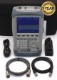
- Anritsu MW8208A Passive Intermodulation Analyzer w/ Option: (BC# 31929-L/T*)
- 0425: Large Wheel Option
- Armored Test Port Cable
- BNC Cable
- Power Cord
- USB PC Interface Cable
Request a Quote for