
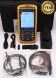

Fluke 123B Industrial ScopeMeter 20MHz
Condition: Refurbished / Calibrated
Warranty: 1 YEAR WARRANTY
Fluke 123B Industrial Scopemeter
Simplified testing, more insight and faster electro-mechanical troubleshooting
The compact ScopeMeter® 120B Series, is the rugged oscilloscope solution for industrial electrical and electro-mechanical equipment troubleshooting and maintenance applications. It’s a truly integrated test tool, with oscilloscope, multimeter and high-speed recorder in one easy-to-use instrument. The ScopeMeter 120B Series also integrates with Fluke Connect® mobile app and FlukeView® for ScopeMeter software to enable further collaboration, data analysis and archiving of critical test information.
The 120B Series Industrial ScopeMeter Test Tools include innovative functions designed to help technicians troubleshoot faster and get the answers they need to keep their systems up and running. Display waveforms with Connect and View™ trigger and setup technology and automatically view related numerical measurements using Fluke IntellaSet™ technology, all without making manual measurement adjustments. With Recorder Event Detect capabilities, elusive intermittent events are captured and logged for easy viewing and analysis.
- Dual-input digital oscilloscope and multimeter
- 20 MHz oscilloscope bandwidth
- Two 5,000-count true-rms digital multimeters
- Connect-and-View™ trigger simplicity for hands-off operation
- IntellaSet™ technology automatically and intelligently adjusts numerical readout based on the measured signal
- Dual-input waveform and meter reading recorder for trending data over extended periods
- Recorder Event Detect captures elusive intermittent signals on repetitive waveforms up to 10 KHz
- Shielded test leads for oscilloscope, resistance and continuity measurements
- Resistance, continuity, diode and capacitance meter measurements
- Power measurements (W, VA, VAR, PF, DPF, Hz)
- Voltage, current and power harmonics
- Check Industrial networks with BusHealth physical layer tests against defined reference levels
- Save or recall data and instrument setups
- Store instrument setups defined by a test sequence for routine maintenance or most often used test procedures.
- External optically isolated USB interface to transfer, archive and analyze scope or meter data
- FlukeView® ScopeMeter® Software for Windows®
- Rugged design to withstand 3g Vibration, 30g shock, and rated IP51 according to EN/IEC60529
- Highest safety rating in the industry: safety rated for CAT IV 600 V
- Li-Ion rechargeable battery, seven-hours operation (with four-hour charge time)
Connect-and-View™ triggering for an instant, stable display
Oscilloscope users know how difficult triggering can be. Using the wrong settings can lead to unstable waveform captures, and sometimes the wrong measurement data. Fluke’s unique Connect-andView™ triggering technology recognizes signal patterns, and automatically sets up the correct triggering to provide a stable, reliable and repeatable display. Connect-and-View™ triggering is designed to work with virtually any signal, including motor drives and control signals— without adjusting parameters, or even touching a button. Signal changes are instantly recognized and settings are automatically adjusted, providing a stable display even when measuring multiple test points in quick succession.
IntellaSet™/AutoReading
The Auto Readings function with Fluke IntellaSet™ technology uses proprietary algorithms to intelligently analyze the measured waveform and automatically displays the most appropriate numerical measurements on screen, so you can get the data you need easier than ever before. As an example, when the measured waveform is a line voltage signal, the Vrms and Hz readings are automatically displayed, whereas if the measured waveform is a square wave, the Vpeak-peak and Hz readings are automatically displayed. Using IntellaSet™ technology in conjunction with Connectand-View™ automatic triggering you can be sure you’re seeing not only the correct waveform, but the appropriate numerical reading as well. All without touching a button.
Industrial equipment needs a reliable power supply to operate properly, use the dual input to obtain key power measurements.
For single phase or 3-phase balanced systems, the dual inputs of the Industrial ScopeMeter® 120B Series can measure ac+dc rms voltage on channel A and ac+dc rms current on channel B. The Fluke 125B can then calculate; frequency, phase angle, active power (kW), reactive power (VA or var), power factor (PF) or displacement power factor (DPF) and can also calculate the power values for a 3-phase system where all phases have equal voltage and currents. This applies to both balanced system and resistive loads.
Harmonics measurements
Harmonics are periodic distortions of voltage, current, or power sine waves. Harmonics in power distribution systems are often caused by non-linear loads such as switched mode dc power supplies and adjustable speed motor drives. Harmonics can cause transformers, conductors, and motors to overheat. In the Harmonics function, the Test Tool measures harmonics to the 51st. Related data such as dc components, THD (Total Harmonic Distortion), and K factor are measured to provide a complete insight in to the electrical state of health of your loads.
One test lead to measure multiple electrical parameters
High frequency waveform, meter, capacitance and resistance measurements as well as continuity checks are all covered by single set of shielded test leads. No time is wasted finding or swapping leads.
Fluke Connect mobile app compatibility
Automated industrial machinery is harder than ever to trouble shoot. It’s not enough to just know where you have to test, you also have to know what to look for—and that can be hard without baseline measurement data or access to subject matter experts. The Fluke Connect® Assets wireless system of software and wireless test tools enables technicians to reduce maintenance costs and increase uptime with accurate equipment records and maintenance data that is easy to interpret, and share. Compare and contrast test point measurement data and trends so you can better understand signal characteristics and changes over time. And, by storing maintenance data on the Fluke Cloud™ you can enable team members to access it from wherever and whenever they need to so you can get advice or approvals in the field and get your systems up and running faster than ever before.
Use the comprehensive recorder modes to help find intermittent faults with ease
The toughest faults to find are those that happen only once in a while—intermittent events. They can be caused by bad connections, dust, dirt, corrosion or simply broken wiring or connectors. Other factors, like line outages and sags or the starting and stopping of a motor, can also cause intermittent events resulting in equipment shutdowns. When these events happen, you may not be around to see it. But, your Fluke ScopeMeter® Test Tool will. You can either plot the minimum and maximum peak measurement values or record the waveform trace. And, with expandable micro SD memory, recording sessions can be done for up to 14 days. This recorder is even more powerful with the addition of Recorder Event Detect, which makes detecting and logging intermittent faults easier than ever. Just set a threshold on a meter reading or scope trace and deviations are tagged as unique events. You no longer need to search through masses of data to pinpoint faults, and can quickly step from one tagged event to the next, while still having access to the full data set.
Industrial Bus Health Test verifies electrical signal quality on industrial buses
Bus Health Test analyzes the electrical signals on the industrial bus or network and gives a clear “Good”, “Weak” or “Bad” indication mark for each of the relevant parameters, presented next to the actual measurement value. Measured values are compared to standard values based on the selected bus types (CAN-bus, Profi-bus, Foundation Field, RS-232 and many more), or, unique reference values can be set if different tolerances are required. The Fluke 125B can validate the quality of the electrical signals as soon as they are passed along the network, without looking at the data content. Additionally, the 125B checks the signal levels and speed, transition times and distortion, and compares these to the appropriate standards to help you find errors such as improper cable connections, bad contacts, incorrect grounding or improper terminators.
Specifiations:
| Oscilloscope mode | ||
| Frequency response - dc coupled |
without probes and test leads (with BB120) | 123B: dc to 20 MHz (-3 dB) |
| with STL120-IV 1:1 shielded test leads | DC to 12.5 MHz (-3 dB) / dc to 20 MHz (-6 dB) | |
| with VP41 10:1 Probe | 123B: dc to 20MHz (-3 dB) | |
| Frequency response - ac coupled (lf roll off) | without probes and test leads | <10 Hz (-3 dB) |
| with STL120-IV 1:1 shielded test leads | <10 Hz (-3 dB) | |
| with VP41 10:1 Probe | <10 Hz (-3 dB) | |
| Rise time, excluding probes, test leads | <17.5 ns | |
| Input impedance | without probes and test leads | 1 MΩ//20 pF |
| with BB120 | 1 MΩ//24 pF | |
| with STL120-IV 1:1 shielded test leads | 1 MΩ//230 pF | |
| with VP41 10:1 Probe | 5 MΩ//15.5 pF | |
| Sensitivity | 5 mV to 200 V/div | |
| Analog bandwidth limiter | 10 kHz | |
| Display modes | A, -A, B, -B | |
| Max. input voltage A and B | direct, with test leads, or with VP41 Probe | 600 Vrms CAT IV, 750 Vrms maximum voltage. |
| Max. floating voltage, from any terminal to ground | 600 Vrms CAT IV, 750 Vrms up to 400Hz | |
| Horizontal | ||
| Scope modes | Normal, Single, Roll | |
| Ranges (Normal) | Equivalent sampling | 123B: 20 ns to 500 ns/div, |
| Real time sampling | 1 μs to 5 s/div | |
| Roll (real time) | 1s to 60 s/div | |
| Sampling rate (for both channels simultaneously) | Equivalent sampling (repetitive signals) | up to 4 GS/s |
| Real time sampling 1 μs to 60 s/div | 40 MS/s | |
| Trigger | ||
| Screen update | Free run, on trigger | |
| Source | A, B | |
| Sensitivity A and B | @ DC to 5 MHz | 0.5 divisions or 5 mV |
| @ 40 MHz | 123B: 4 divisions | |
| Slope | Positive, negative | |
| Advanced scope functions | ||
| Display modes | Normal | Captures up to 25 ns glitches and displays analog-like persistence waveform. |
| Smooth | Suppresses noise from a waveform. | |
| Glitch off | Does not capture glitches between samples | |
| Envelope | Records and displays the minimum and maximum of waveforms over time. | |
| Auto set (Connect-and-View™) | Continuous fully automatic adjustments of amplitude, time base, trigger levels, trigger gap, and hold-off. Manual override by user adjustment of amplitude, time base, or trigger level. | |
| Dual input meter | ||
| The accuracy of all measurements is within ± (% of reading + number of counts) from 18 °C to 28 °C. | ||
| Add 0.1x (specific accuracy) for each °C below 18 °C or above 28 °C. For voltage measurements with 10:1 probe, add probe uncertainty +1 %. More than one waveform period must be visible on the screen. | ||
| Input A and input B | ||
| DC voltage (VDC) | ||
| Ranges | 500 mV, 5 V, 50 V, 500 V, 750 V | |
| Accuracy | ± (0.5 % +5 counts) | |
| Common mode rejection (CMRR) | >100 dB @ dc, >60 dB @ 50, 60, or 400 Hz | |
| Full scale reading | 5000 counts | |
| True-rms voltages (V ac and V ac+dc) | ||
| Ranges | 500 mV, 5 V, 50 V, 500 V, 750 V | |
| Accuracy for 5 % to 100 % of range (DC coupled) | DC to 60 Hz (V ac+dc) | ± (1 % +10 counts) |
| 1 Hz to 60 Hz (V ac) | ± (1 % +10 counts) | |
| Accuracy for 5 % to 100 % of range (AC or dc coupled) | 60 Hz to 20 kHz | ± (2.5 % +15 counts) |
| DC rejection (only VAC) | >50 dB | |
| Common mode rejection (CMRR) | >100 dB @ dc >60 dB @ 50, 60, or 400 Hz |
|
| Full scale reading | 5000 counts, reading is independent of any signal crest factor. | |
| Peak | ||
| Modes | Max peak, Min peak, or pk-to-pk | |
| Ranges | 500 mV, 5 V, 50 V, 500 V, 2200 V | |
| Accuracy | Accuracy Max peak or Min peak | 5 % of full scale |
| Accuracy Peak-to-Peak | 10 % of full scale | |
| Full scale reading | 500 counts | |
| Frequency (Hz) | ||
| Ranges | 123B: 1 Hz, 10 Hz, 100 Hz, 1 kHz, 10 kHz, 100 kHz,1 MHz, 10 MHz, and 50 MHz | |
| Frequency range | 15 Hz (1 Hz) to 50 MHz in continuous autoset | |
| Accuracy @1 Hz to 1 MHz | ± (0.5 % +2 counts) | |
| Full scale reading | 10 000 counts | |
| RPM | ||
| Max reading | 50.00 kRPM | |
| Accuracy | ± (0.5 % +2 counts) | |
| Duty cycle (PULSE) | ||
| Range | 2 % to 98 % | |
| Frequency range | 15 Hz (1 Hz) to 30 MHz in continuous autoset | |
| Pulse width (PULSE) | ||
| Frequency range | 15 Hz (1 Hz) to 30 MHz in continuous autoset | |
| Full scale reading | 1000 counts | |
| Amperes (AMP) | ||
| With current clamp | Ranges | same as V dc, V ac, V ac+dc, or PEAK |
| Scale factors | 0.1 mV/A, 1 mV/A, 10 mV/A, 100 mV/A, 400 mV/A, 1 V/A, 10 mV/mA | |
| Accuracy | same as V dc, V ac, V ac+dc, or PEAK (add current clamp uncertainty) | |
| Temperature (TEMP) with optional temperature probe | ||
| Range | 200 °C/div (200 °F/div) | |
| Scale factor | 1 mV/°C and 1 mV/°F | |
| Accuracy | as V dc (add temp. probe uncertainty) | |
| Decibel (dB) | ||
| 0 dBV | 1 V | |
| 0 dBm (600 Ω /50 Ω) | 1 mW referenced to 600 Ω or 50 Ω | |
| dB on | V dc, V ac, or Vac+dc | |
| Full scale reading | 1000 counts | |
| Crest factor (CREST) | ||
| Range | 1 to 10 | |
| Full scale reading | 90 Counts | |
| Phase | ||
| Modes | A to B, B to A | |
| Range | 0 to 359 degrees | |
| Resolution | 1 degree | |
| Vpwm | ||
| Purpose | to measure on pulse width modulated signals, like motor drive inverter outputs | |
| Principle | readings show the effective voltage based on the average value of samples over a whole number of periods of the fundamental frequency | |
| Accuracy | as Vrms for sinewave signals | |
| Input A to common | ||
| Ohm (Ω) | ||
| Ranges | 500 Ω , 5 kΩ, 50 kΩ, 500 kΩ, 5 MΩ, 30 MΩ | |
| Accuracy | ± (0.6 % + 5 counts) 50 Ω ±(2 % + 20 counts) | |
| Full scale reading | 50 Ω to 5 MΩ - 5000 counts, 30 MΩ - 3000 counts | |
| Measurement current | 0.5 mA to 50 nA, decreases with increasing ranges | |
| Open circuit voltage | <4 V | |
| Continuity (Cont) | ||
| Beep | <(30 Ω ± 5 Ω) in 50 Ω range | |
| Measurement current | 0.5 mA | |
| Detection of shorts of | ≥1 ms | |
| Diode | ||
| Measurement voltage | @0.5 mA | >2.8 V |
| @open circuit | <4 V | |
| Measurement current | 0.5 mA | |
| Polarity | + on input A, - on COM | |
| Capacitance (CAP) | ||
| Ranges | 50 nF, 500 nF, 5 μF, 50 μF, 500 μF | |
| Full scale reading | 5000 counts | |
| Measurement current | 500 nA to 0.5 mA, increases with increasing ranges | |
| Advanced meter functions | ||
| Zero Set | Set actual value to reference | |
| AutoHold (on A) Captures and freezes a stable measurement result. Beeps when stable. AutoHold works on the main | Captures and freezes a stable measurement result. Beeps when stable. AutoHold work | |
| Fixed decimal point | Activated by using attenuation keys. | |
| Recorder | ||
| The results are displayed as Chart recorder display that plots a graph of min and max values of Meter measurements over time or as a waveform recorder display that plots all the captured samples. | ||
| Meter readings | ||
| Measurement Speed | Maximum 2 measurements/s | |
| Record Size (min, max, average) | 2 M readings for 1 channel | |
| Recorded Time Span | 2 weeks | |
| Maximum number of events | 1024 | |
| Waveform record | ||
| Maximum sample rate | 400 K sample/s | |
| Size Internal memory | 400 M samples Recorded Time | |
| Span internal memory | 15 minutes at 500 μs/div | 11 hours at 20 ms/div |
| Record Size SD card | 1.5 G samples | |
| Recorded Time Span SD card | 11 hours at 500 μs/div | 14 days at 20 ms/div |
| Maximum number of events | 64 | |
| Miscellaneous | ||
| Display | Type | 5.7-inch color active matrix TFT |
| Resolution | 640 x 480 pixels | |
| Waveform Display | Vertical | 10 div of 40 pixels |
| Horizontal | 12 div of 40 pixels | |
| Power | External | via Power Adapter BC430 |
| Input voltage | 10 V DC to 21 V DC | |
| Power consumption | 5 W typical | |
| Input connector | 5 mm jack | |
| Internal | via Battery Pack BP290 | |
| Battery power | 7 hours with 50 % backlight brightness | |
| Charging time | 4 hours with test tool off, 7 hours with test tool on | |
| Allowable ambient temp | 0 to 40 °C (32 to 104 °F) during charging | |
| Memory | Internal memory can store 20 data sets (screen waveform and setup) | Micro SD card slot with optional SD card (max size of 32 GB) |
| Mechanical | Size | 259 mm x 132 mm x 55 mm (10.2 in x5.2 in x 2.15 in) |
| Weight | 1.4 kg (3.2 lb) including battery pack | |
| Interface | Optically isolated | Transfer screen copies (bitmaps), settings and data |
| USB to PC/laptop | OC4USB optically isolated USB adapter/cable, (optional), using FlukeView® software for Windows® | |
| Optional WiFi adapter | Fast transfer of screen copies (bitmaps), settings and data to PC/laptop, tablet, smartphone, etc. A USB port is provided for attaching the WiFi dongle. Do not use the USB port with a cable for safety reasons. | |
| Environmental | ||
| Environmental | MIL-PRF-28800F, Class 2 | |
| Temperature | Battery Operation | 0 to 40 °C (32 to 104 °F) |
| Power Adapter Operation | 0 to 50 °C (32 to 122 °F) | |
| Storage | -20 to 60 °C (-4 to 140 °F) | |
| Humidity (Operating) | @ 0 to 10 °C (32 to 50 °F) | noncondensing |
| @ 10 to 30 °C (50 to 86 °F) | 95 % | |
| @ 30 to 40 °C (86 to 104 °F) | 75 % | |
| @ 40 to 50 °C (104 to 122 °F) | 45 % | |
| Storage | @ -20 to 60 °C (-4 to 140 °F) | noncondensing |
| Altitude | Operating at 3 km (10 000 feet) | CAT III 600 V |
| Operating at 2 km (6 600 feet) | CAT IV 600 V | |
| Storage | 12 km (40 000 feet) | |
| EMC electromagnetic compatibility | International | IEC 61326-1: Industrial, CISPR 11: Group 1, Class A |
| Korea (KCC) | Class A Equipment (Industrial Broadcasting & Communication Equipment) | |
| USA (FCC) | 47 CFR 15 subpart B. This product is considered an exempt device per clause 15.103. | |
| Wireless radio with adapter | Frequency range | 2412 MHz to 2462 MHz |
| Output power | <100 mW | |
| Enclosure protection | IP51, ref: EN/IEC60529 | |
| Safety | General | IEC 61010-1: Pollution Degree 2 |
| Measurement | IEC 61010-2-033: CAT IV 600 V/CAT III 750 V | |
| Max. input voltage input A and B | Direct on input or with leads | 600 Vrms CAT IV for derating |
| With Banana-to BNC Adapter BB120 | 600 Vrms for derating | |
| Max. floating voltage from any terminal to ground | 600 Vrms CAT IV, 750 Vrms up to 400 Hz | |
For full Fluke 123B product specifications, please click here: Fluke 123B
Fluke 123B industrial Scopemeter
A truly integrated test tool, with oscilloscope, multimeter and high-speed recorder in one easy-to-use instrument.
Includes Carrying Case & Accessories As Listed
Fluke 123B Fluke-123B Scopemeter Models On Sale Warranty Calibration Backed by The Best Service and Lowest Prices in the Industry.
BC# 35501-L/T*
- Fluke 123B Industrial Scopemeter (BC# 35501-L/T*)
- (2) Fluke Voltage Probes
- Fluke 1000V hard Point Test Lead
- AC Adapter/Charger
- Power Cord
- User Manual On CD-ROM
- Carrying Case (G)