
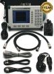

JDSU JD724C CellAdvisor Cable & Antenna Analyzer
$4,995.00
Availability:
Out of stock
SKU
6C102
Condition: Refurbished / Calibrated
Warranty: 90 Day Exchange
Request a Quote for
JDSU JD724C CellAdvisor Cable & Antenna Analyzer
The majority of problems in mobile networks occur in the base stationメs infrastructure, consisting of the antenna system, RF and fiber cables, and connectors. Properly servicing and installing cell sites requires suitable test equipment. JDSU CellAdvisor JD720C analyzers are the optimal test solutions for characterizing cell-site infrastructure due to their handheld design, ease of use, and rich functionality.
JD720C analyzers have all of necessary measurement functions to characterize cell-site cable and antenna system, including VSWR or return loss reflection tests, distance to fault (DTF), and cable loss. It also can perform RF component measurements, including insertion gain/loss, antenna isolation, TMA performance, and verification of devices such as duplexers and combiners.
The instrumentメs 7-inch color touch-screen display simplifies its operation and clearly displays measurement results. Its connectivity to JDSU application software allows for easier measurement analysis and report generation.
In addition, JD720 analyzers are capable of fiber inspection using the JDSU fiber microscope and optical power measurement using JDSU optical power meters. This single integrated solution with RF and fiber capabilities provides all the physical layer tests needed for the installation and maintenance of cell sites.
Key measurements include:
Reflection measures the cell-site transmission line impedance performance across the selected frequency range in VSWR or Return Loss.
Fiber Inspection eliminates the most common fiber link problems by verifying that connectors are not contaminated. Interfacing with a JDSU fiber microscope, fiber connectors can be quickly inspected with a clear pass/fail indication. The FiberChekPROル application can be used on a PC/laptop with the fiber microscope to perform the same fiber analysis in parallel using the instrument to test RF and using the PC/laptop to test fiber. Users also can inspect, test, and certify any fiber connector and instantly generate comprehensive pass/fail summary reports with the optical power meterメs results.
Key Benefits
Designed for Field Use
Compact, lightweight JD720C analyzers are especially convenient for performing measurements in the field. The analyzers weigh less than 2.35 kg (fully loaded) and include a lithium ion (LiON) battery that lasts more than 7.5 hours.
Its transflective display can be set to an outdoor mode for viewing measurements in direct sunlight. Also, its backlit key panel with Night Display mode makes it easy to use in the dark.
JD720C analyzers operate in ヨ10 to +55°C temperatures; and its rugged bumper design protects it for filed use, such as drop and vibration, complying with MIL-PRF-28800F class 2 specification.
Quickly Sweeps
It can perform measurements in less than 0.8 ms/point, making these the fastest cable and antenna analyzers on the market with uncompromising fast sweep speed in Dual Display mode.
Multilanguage User Interface
The instrumentsメ architecture can incorporate different languages into the menu structure.
Easy to Use
Users can create favorite keys to conveniently access repeatedly used measurements rather than configuring them each time, reducing steps and completing tasks quicker and more efficiently. They can add editable key words to quickly create unique file names and can generate a PDF report directly from the instrument.
Key Features
Trace Overlay
Allows users to compare and analyze up to four traces by superimposing them into one measurement display. Additionally, up to six markers can be set on any trace independently
Zoom Zones
User-definable frequency zones can be set to visually identify sub-band regions such as uplink and downlink frequencies to verify compliance within a single measurement and independent view for closer analysis of each zone.
Alternate Sweep in DTF
Allows users to perform two independent sweeps and to display the measurements, such as a reflection and a DTF, in the same window.
Dual Display
Provides the ability to display two measurements simultaneously, reducing test time.
Peak and Valley All Zones
Allows users to easily and automatically set markers to identify the trace peaks and valleys in each zone.
Limit Lines
Limit lines let users set variable testing thresholds with automatic pass/fail indication.
Standard Limit Line
The standard limit line extends over the full measurement frequency range and can be configured to indicate a fail when measurements exceed it. Users can also set a limit line for only specific sections.
Multisegment Limit Line(MSL)
Multisegment limits let users set upper- and lower-level thresholds for greater flexibility than single limit lines. Measurements falling within the mutisegment limit line boundaries are indicated as pass, while measurements outside the boundaries are indicated as fail.
Window Limit
Window limit lets users define a measurement area in which to apply the test criteria. Measurements within the configured area are compared to the defined threshold and are indicated as pass/fail based on whether they fall within or outside the threshold. This capability is useful for tuning devices or antennas in real time.
Help Function
The Help function gives users task-based information related to instrument operation or the test performed. Users can then easily browse or search topics to get specific information.
Specifications:
The majority of problems in mobile networks occur in the base stationメs infrastructure, consisting of the antenna system, RF and fiber cables, and connectors. Properly servicing and installing cell sites requires suitable test equipment. JDSU CellAdvisor JD720C analyzers are the optimal test solutions for characterizing cell-site infrastructure due to their handheld design, ease of use, and rich functionality.
JD720C analyzers have all of necessary measurement functions to characterize cell-site cable and antenna system, including VSWR or return loss reflection tests, distance to fault (DTF), and cable loss. It also can perform RF component measurements, including insertion gain/loss, antenna isolation, TMA performance, and verification of devices such as duplexers and combiners.
The instrumentメs 7-inch color touch-screen display simplifies its operation and clearly displays measurement results. Its connectivity to JDSU application software allows for easier measurement analysis and report generation.
In addition, JD720 analyzers are capable of fiber inspection using the JDSU fiber microscope and optical power measurement using JDSU optical power meters. This single integrated solution with RF and fiber capabilities provides all the physical layer tests needed for the installation and maintenance of cell sites.
Key measurements include:
- Reflection ラ VSWR/Return Loss
- DTF ラ VSWR/Return Loss
- 1-Port Cable Loss
- 1-Port Phase
- Smith Chart
- RF and Optical Power Meter
- Fiber Inspection
Reflection measures the cell-site transmission line impedance performance across the selected frequency range in VSWR or Return Loss.
- The instrumentメs database includes over 80 wireless frequency bands with the ability to add more.
- A user-definable limit line automatically indicates pass/fail status.
- Users can set up to six markers for trace analysis
- Cable length up to 1,500 m (4,921 ft)
- High-resolution mode with 2001 data points.
- The instrumentメs database includes over 95 cable types with the ability to add more.
- A user-definable limit line automatically indicates pass/fail status
- Users can set up to six markers for trace analysis.
- A user-definable limit line automatically indicates pass/fail status
- Users can set up to six markers for trace analysis
- Users can set up to six markers for trace analysis.
- Users can set up to six markers for trace analysis
- JD72450551/2: economic RF power sensors via serial connection
- JD730 series: high-precision RF power sensors via USB connection
- MP-60/MP-80: optical power meters via USB connection
Fiber Inspection eliminates the most common fiber link problems by verifying that connectors are not contaminated. Interfacing with a JDSU fiber microscope, fiber connectors can be quickly inspected with a clear pass/fail indication. The FiberChekPROル application can be used on a PC/laptop with the fiber microscope to perform the same fiber analysis in parallel using the instrument to test RF and using the PC/laptop to test fiber. Users also can inspect, test, and certify any fiber connector and instantly generate comprehensive pass/fail summary reports with the optical power meterメs results.
Key Benefits
Designed for Field Use
Compact, lightweight JD720C analyzers are especially convenient for performing measurements in the field. The analyzers weigh less than 2.35 kg (fully loaded) and include a lithium ion (LiON) battery that lasts more than 7.5 hours.
Its transflective display can be set to an outdoor mode for viewing measurements in direct sunlight. Also, its backlit key panel with Night Display mode makes it easy to use in the dark.
JD720C analyzers operate in ヨ10 to +55°C temperatures; and its rugged bumper design protects it for filed use, such as drop and vibration, complying with MIL-PRF-28800F class 2 specification.
Quickly Sweeps
It can perform measurements in less than 0.8 ms/point, making these the fastest cable and antenna analyzers on the market with uncompromising fast sweep speed in Dual Display mode.
Multilanguage User Interface
The instrumentsメ architecture can incorporate different languages into the menu structure.
Easy to Use
Users can create favorite keys to conveniently access repeatedly used measurements rather than configuring them each time, reducing steps and completing tasks quicker and more efficiently. They can add editable key words to quickly create unique file names and can generate a PDF report directly from the instrument.
Key Features
Trace Overlay
Allows users to compare and analyze up to four traces by superimposing them into one measurement display. Additionally, up to six markers can be set on any trace independently
Zoom Zones
User-definable frequency zones can be set to visually identify sub-band regions such as uplink and downlink frequencies to verify compliance within a single measurement and independent view for closer analysis of each zone.
Alternate Sweep in DTF
Allows users to perform two independent sweeps and to display the measurements, such as a reflection and a DTF, in the same window.
Dual Display
Provides the ability to display two measurements simultaneously, reducing test time.
Peak and Valley All Zones
Allows users to easily and automatically set markers to identify the trace peaks and valleys in each zone.
Limit Lines
Limit lines let users set variable testing thresholds with automatic pass/fail indication.
Standard Limit Line
The standard limit line extends over the full measurement frequency range and can be configured to indicate a fail when measurements exceed it. Users can also set a limit line for only specific sections.
Multisegment Limit Line(MSL)
Multisegment limits let users set upper- and lower-level thresholds for greater flexibility than single limit lines. Measurements falling within the mutisegment limit line boundaries are indicated as pass, while measurements outside the boundaries are indicated as fail.
Window Limit
Window limit lets users define a measurement area in which to apply the test criteria. Measurements within the configured area are compared to the defined threshold and are indicated as pass/fail based on whether they fall within or outside the threshold. This capability is useful for tuning devices or antennas in real time.
Help Function
The Help function gives users task-based information related to instrument operation or the test performed. Users can then easily browse or search topics to get specific information.
Specifications: