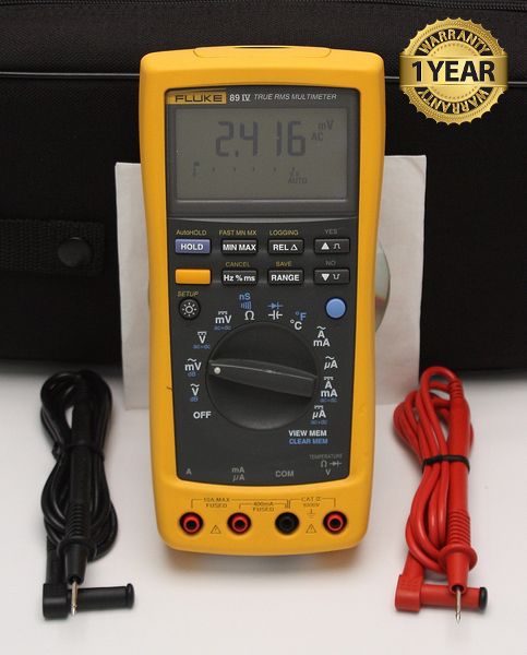

Fluke 89 IV True RMS Digital Multimeter
Condition: Refurbished
Warranty: 1 YEAR WARRANTY
Shipping: USA & Worldwide
- Fluke 89 IV True RMS Digital Multimeter (BC# 32493-L/T*)
- (2) 1000V Hard Point Test Leads
- User Manual ON CD-ROM
- Carrying Case (G)
The top-of-the line Fluke 89 Series IV, in stand-alone operation, can log up to 1000 measurements. The PC interface allows for further analysis and documentation using optional FlukeView ル software. It sounds like a lot to get in one DMM. But what else do you expect from Fluke?
Nominal Specifications
| Function | Ranges/Description |
| DC Voltage | 0 to 1000V |
| DC Current | 0 to 10A (20A for 30 seconds) |
| AC Voltage, True-rms | 15 mV to 1000V - 100 kHz bandwidth |
| AC Current, True-rms | 25 µA to 10A (20A for 30 seconds) |
| Resistance | 0 to 30 Mohms |
| Conductance | 0 to 50 Nanosiemens |
| Capacitance | 0.01 nF to 50 mF |
| Diode Test | 3.1V |
| Temperature | -200°C to 1350°C (-328°F to 2462°F) |
| Frequency | 0.5 Hz to 1000 kHz |
| Accuracy (Basic DC V) | 0.025% |
| (Basic AC V) | 0.4% |
Features
| Feature | Description |
| Dual Displays | 50,000 count primary display 5,000 count secondary display |
| Backlight with 2 brightness selections | Bright white backlight for clear readings in poorly lighted areas |
| Fast Autorange | Meter automatically selects best range -instantly |
| AC+DC True RMS, ac rms specified to 100 kHz | Choices for AC only, AC and DC dual display, or AC+DC readings |
| dBm, dBV | User selectable impedance references for dBm |
| AutoHOLD | Uses Touch Hold® feature to capture readings |
| Continuity/Open Test | Beeper sounds for Ohms readings below threshold or for momentary open circuit indication |
| Fast Bar Graph | 51 Segments for peaking and nulling |
| Duty Cycle/Pulse Width | Measure time a signal is on or off in % or milliseconds |
| MIN MAX/Fast MIN MAX with elapsed and Real Time Stamp | Record Maximum, Minimum, and Average values. Real Time for MAX or MIN, elapsed time for AVG. Fast MIN MAX captures peaks to 250 msec. |
| Closed Case Calibration | No internal adjustments needed |
| Battery/Fuse Access Door | Battery or fuse replacement without voiding calibration |
| Hi-Impact Overmold Case | Integrated Protective Holster provides superior impact protection for your meter |
Detailed Specifications
Accuracy is specified for a period of one year after calibration, at 18°C to 28°C (64°F to 82°F) with
relative humidity to 90%. Accuracy specifications are given as ±([% of reading] + [number of least
significant digits])
| Function | Range | Resolution | Accuracy | ||||
| 45 Hz-1 kHz | 20 Hz-45 Hz | 1 kHz-10 kHz | 10 kHz-20 kHz | 20 kHz-100 kHz | |||
| AC mV | 500.00 mV | 0.01 mV | 0.4% + 40 | 2% + 80 | 5% + 40 | 5% + 40 | 6% + 40 |
| 3000.0 mV | 0.1 mV | 0.4% + 40 | 2% + 80 | 0.4% + 40 | 1.5% + 40 | 6% + 40 | |
| AC V | 5.0000V | 0.0001V | 0.4% + 40 | 2% + 80 | 0.4% + 40 | 1.5% + 40 | 6% + 40 |
| 50.000V | 0.001V | 0.4% + 40 | 2% + 80 | 0.4% + 40 | 1.5% + 40 | 6% + 40 | |
| 500.00V | 0.01V | 0.4% + 40 | 2% + 80 | 0.4% + 40 | Not specified | Not specified | |
| 1000.0V | 0.1V | 0.4% + 40 | 2% + 80 | 0.4% + 40 | Not specified | Not specified | |
| dBV | -56 to -6 | 0.01 dB | 0.1 dB | 0.2 dB | 0.5 dB | 0.5 dB | 0.5 dB |
| -6 to +34 | 0.01 dB | 0.1 dB | 0.2 dB | 0.1 dB | 0.2 dB | 0.5 dB | |
| +34 to +60 | 0.01 dB | 0.1 dB | 0.2 dB | 0.1 dB | Not specified | Not specified | |
| Accuracy | ||||||
| Function | Range | Resolution | 45 Hz-1 kHz | 20 Hz-45 Hz | 1 kHz-20 kHz | 20 kHz-100 kHz |
| AC mA | 500.00 µA | 0.01 µA | 0.75% + 20 | 1% + 20 | 0.75% + 20 | 6% + 4 |
| 5.000 µA | 0.1 µA | 0.75% + 5 | 1% + 5 | 0.75% + 10 | 2% + 40 | |
| AC mA | 50.000 mA | 0.001 mA | 0.75% + 20 | 1% + 20 | 0.75% + 20 | 9% + 40 |
| 400.00 mA | 0.01 mA | 0.75% + 5 | 1% + 5 | 1.5% + 10 | 4% + 4 | |
| AC A | 5.0000A | 0.0001A | 1.5% + 20 | 1.5% + 20 | 6% + 40 | Not specified |
| 10.000A | 0.001A | 1.5% + 5 | 1.5% + 5 | 5% + 10 | Not specified | |
| Function | Range | Resolution | DC | Accuracy Dual Display AC or AC+DC | ||
| 20 Hz-45 Hz | 45 Hz-1 kHz | 1kHz-20 kHz | ||||
| DC mV | 500.00 mV | 0.01 mV | 0.03% + 2 | 2% + 80 | 0.6% + 40 | 6% + 40 |
| 3000.0 mV | 0.1 mV | 0.025% + 5 (89-IV) 0.025% + 10 (87-IV) | 2% + 80 | 0.6% + 40 | ||
| DC V | 5.0000V | 0.0001V | 0.025% + 10 | 2% + 80 | 0.5% + 40 | |
| 50.000V | 0.001V | 0.03% + 3 | 2% + 80 | 0.5% + 40 | ||
| 500.00V | 0.01V | 0.1% + 2 | 2% + 80 | 0.5% + 40 | Not specified | |
| 1000.0V | 0.1V | 0.1% + 2 | 2% + 80 | 0.5% + 40 | Not specified | |
| DC mA | 500.00 mA | 0.01 mA | 0.25% + 20 | 7% + 10 | 7% + 10 | 9% + 40 |
| 5.000 mA | 0.1 mA | 0.25% + 2 | 1% + 10 | 0.75% + 10 | 2% + 40 | |
| DC mA | 50.000 mA | 0.001 mA | 0.15% + 10 | 1% + 10 | 0.75% + 10 | 2% + 40 |
| 400.00 mA | 0.01 mA | 0.15% + 2 | 1.5% + 10 | 1.5% + 10 | 3% + 40 | |
| DC A | 5.0000A | 0.0001A | 0.5% + 10 | 7% + 20 | 7% + 20 | 12% + 40 |
| 10.000A | 0.001A | 0.5% + 2 | 1.5% + 10 | 1.5% + 10 | 3% + 40 | |
Accuracy is specified for a period of one year after calibration, at 18°C to 28°C (64°F to 82°F) with relative humidity to 90%. Accuracy specifications are given as ±([% of reading] + [number of least significant digits])
| Function | Range | Resolution | Accuracy |
| Resistance | 500.00W | 0.01W | 0.05% + 10 |
| 5.0000 kW | 0.0001 kW | 0.05% + 2 | |
| 50.000 kW | 0.001 kW | 0.05% + 2 | |
| 500.00 kW | 0.01 kW | 0.05% + 2 | |
| 5.0000 MW | 0.0001 MW | 0.15% + 4 | |
| 30.000 MW | 0.001 MW | 1% + 4 | |
| Conductance | 50.00 nS | 0.01 nS | 1% + 10 |
| Capacitance | 1.100 nF | 0.001 nF | 1% + 5 |
| 11.00 nF | 0.01 nF | ||
| 110.0 nF | 0.1 nF | ||
| 1.100 mF | 0.001 mF | ||
| 11.00 mF | 0.01 mF | ||
| 110.0 mF | 0.1 mF | ||
| 1,100 mF | 1 mF | ||
| 11.0 mF | 0.01 mF | ||
| 50.00 mF | 0.01 mF | ||
| Diode Test | 3.1000V | 0.0001V | 2% + 2 |
| Frequency | 500.00 Hz | 0.01 Hz | ± (0.005% + 1) |
| 5.0000 kHz | 0.0001 kHz | ||
| 50.000 kHz | 0.001 kHz | ||
| 999.99 kHz | 0.01 kHz | ||
| Duty Cycle | 10 to 90% | 0.10% | ± (0.12 x Voltage Range/ Input Voltage x 100%) |
| Pulse Width | 5.0000 ms | 0.0001 ms | ± (0.0001 ms + 1) |
| 50.000 ms | 0.001 ms | ||
| Temperature | -200 to +1350°C | 0.1°C | ± (1% of reading + 1°C) |
| -328 to +2462°F | 0.1°F | ± (1% of reading + 1.8°F) | |
| Min-Max-Avg | Response: 100 ms to 80% | Specifed accuracy ± 12 counts for changes >200 ms in duration (± 40 digits in AC for changes >350 ms and inputs >25% of range) | |
| Fast Min-Max | 250 ms | Specified accuracy ± 100 counts for changes >250 ms in duration | |
| Interval LOGGING | At least 288 intervals (specified by user in Setup) may be recorded to internal memory. These values may be viewed using the VIEW MEM function on the meter. Up to 700 unstable event values (similar to AutoHold) are automatically added to LOGGING memory for viewing only through the optional FlukeView® Forms PC software. Additional intervals will be logged if the signal is stable. |
| Reading SAVE | Up to 100 readings may be saved by the user in a memory separate from LOGGING memory. These readings may be viewed using VIEW MEM. |
Frequency Counter Sensitivity
| Input Range | Minimum Sensitivity (RMS Sine Wave) | Approximate Trigger Levels (DC Voltage Function) |
||
| 20 kHz | 40 Hz | 500 kHz | ||
| 50 mV (dB only) | 10 mV | 15 mV | 15 mV | ± 25 mV |
| 500 mV | 100 mV | 50 mV | 30 mV | 35 mV ± 6 mV |
| 5000 mV | 1000 mV | 2000 mV | 2000 mV | 170 mV ± 6 mV |
| 5V | 1V | 2V | 2.2V | 1.7V ± 0.25V |
| 50V | 10V | 15V | 5V | 3.5V ± 2.5V |
| 500V | 100V | 50V | 50V | 35V ± 25V |
| 1000V | 200V | 250V | 50V | 35V ± 25V |
Input Impedance
| Function | Input Impedance (Nominal) | |||||
| Volts, mV | 10 MO, < 100 pF | |||||
| Common Mode Rejection Ratio (1 kO Unbalanced) | Normal Mode Rejection | |||||
| DC Volts, mV | >100 dB -dc, 50 Hz, or 60 Hz ± 0.1% | >90 dB at 50 Hz, or 60 Hz ± 0.1% | ||||
| AC Volts, mV | > 90 dB dc to 60 Hz | |||||
| Open Circuit Test Voltage | Full-Scale Voltage | |||||
| To 5 MO | 30 MO + nS | |||||
| Ohms | < 5V | 500 mV | 3.1V | |||
| Diode Test | < 5V | 3.1000V | ||||
| Typical Short-Circuit Current | ||||||
| 500O | 5 kO | 50 kO | 500 kO | 5 MO | 30 MO | |
| Ohms | 100 µA | 100 µA | 10 µA | 1 µA | 0.1 µA | 0.1 µA |
| Diode Test | 0.8 mA typical | |||||
Burden Voltage (A - mA - µA)
| Function | Range | Burden Voltage (typical) |
| mA -µA | 500.00 µA | 102 µV/µA |
| 5.000 µA | 102 µV/µA | |
| 50.000 mA | 1.8 mV/mA | |
| 400.00 mA | 1.8 mV/mA | |
| A | 5.0000A | 0.04 V/A |
| 10.000A | 0.04 V/A |
Includes:
- Fluke 89 IV True RMS Digital Multimeter
- Fluke 1000V Hard Point Test Leads (1 Red - 1 Black)
- User Manual On CD-ROM
- Carrying Case
For full Fluke 89 IV specifications, please click here: Fluke 89 IB