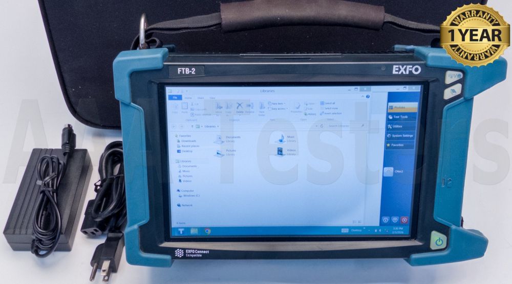


Exfo FTB-2 FTB-740C-DWC-EA DWDM OTDR
Condition: Refurbished / Calibrated
Warranty: 1 Year Warranty
Shipping: USA & Worldwide
- EXFO FTB-2 Mainframe (BC# -L/T*)
- EXFO FTB-740C-DWC-EA DWDM OTDR Module w/ Options: (BC# -L/T*)
- OTDR
- AC Adapter/Charger
- Power Cord
- Carrying Case
EXFO FTB-2 Platform
OPTICAL PLUG-AND-PLAY OPTIONS
The platform features optical plug-and-play options that can be purchased whenever you need them: at the time of your order or later on. In either case, installation is a snap and can be performed by the user without the need for any software update.
Optical Power Meter
A high-level power meter (GeX) that can measure up to 27 dBm, the highest in the industry. This is essential for hybrid fiber-coaxial (HFC) networks or high-power signals. If used with an auto-lambda/auto-switching compatible light source, the power meter automatically syncs on the same wavelength, thus avoiding any risk of mismatched measurement.
- Extensive range of connectors
- Auto-lambda and auto-switching
- Offers measurement storage and reporting
- Choice of seven standard or coarse wavelength-division multiplexing (CWDM)-calibrated wavelengths
Visual Fault Locator (VFL)
The plug-and-play VFL easily identifies breaks, bends, faulty connectors and splices, in addition to other causes of signal loss. This basic, yet essential, troubleshooting tool should be part of every field technician's toolbox. The VFL visually locates and detects faults over distances of up to 5 km by creating a bright-red glow at the exact location of the fault on singlemode or multimode fibers (available with the Optical Power Meter only).
Specifications:
| Display | Touchscreen, color, 1280 × 800 TFT 256 mm (10.1 in) |
| Interfaces | RJ45 LAN 10/100/1000 Mbit/s Two USB 2.0 ports One USB 3.0 port Display port Headset jack |
| Storage (internal flash memory) | 64 GB |
| Battery | One rechargeable Li-ion smart battery |
| Power Supply | AC/DC adapter, input: 100 – 240 V; 50/60 Hz; 2.5 A max, output: 24 V; 3.75 A |
| Computer | Dual-core processor/4 GB RAM/Windows 10 |
| GENERAL SPECIFICATIONS | |
| Size (H × W × D) | 199 mm × 333 mm × 119 mm (7 13/16 in × 13 1/8 in × 4 11/16 in) |
| Weight | 3 kg (6.6 lb) |
| Temperature | Operating: 0 °C to 50 °C (32 °F to 122 °F) Storage: –40 °C to 60 °C (–40 °F to 140 °F) |
| Relative humidity | ≤95 % non-condensing |
EXFO FTB-740C-DWC-EA DWDM OTDR Module
WAVELENGTH-DIVISION MULTIPLEXING BASICS
Wavelength-division multiplexing (WDM) is a technology that multiplexes (aggregates) several optical carrier signals onto a single optical fiber link by using different wavelengths to increase the bandwidth of an optical fiber link.
CWDM VS. DWDM
Besides traditional WDM that relies on 1310 nm and 1550 nm, there are two main patterns aggregating a greater number of wavelengths/signals that have been widely used to expand the capacity of a network without adding more fiber: coarse wavelength division multiplexing (CWDM) and dense wavelength division multiplexing (DWDM). CWDM uses up to 18 wavelengths, from 1271 nm to 1611 nm, with a channel spacing of 20 nma. DWDM has been mainly deployed over the C-Band (1525–1565 nm) with channel spacing from 1.6 nm (200 GHz) to 0.4 nm (50 GHz)
APPLICATIONS
CWDM and DWDM are gaining popularity for C-RAN or commercial services deployments in which each wavelength can address a specific site, such as a cell tower or a customer. Both CWDM and DWDM approaches are not mutually exclusive and co-exist in hybrid passive networks that feature DWDM over CWDM to maximize fiber capacity
Point-to-multipoint xWDM systems (CWDM and/or DWDM) in access networks, such as C‑RAN or commercial services deployments, feature different topologies than in metro/core networks. In these scenarios, it is critical to ensure link continuity, meaning that the right wavelength is connected to the right port on the WDM multiplexer (MUX), demultiplexer (DEMUX) or optical add-drop modules (OADM). Wavelengths must be dropped at the right site by using the right OADM, and by connecting the fiber to the right port. It is a simple but very common issue in access networks of cable operators or fronthaul rings that could be avoided or fixed on-site before leaving the job site. An OTDR using the same channel/wavelength to test through MUX/DEMUX/OADM can provide users, from a single-ended, single operator, with a complete view of the link and total loss budget. Knowing the actual distances between the head‑end and the target site, an OTDR can confirm that a wavelength is properly addressed.
| Specifications | |
| Laser nominal wavelength (nm) | C-Band tunable 1527.99-1567.95 nm ITU-T G694.1 Channels 12-62 (191.2 THz - 196.2 THz) |
| Central wavelength uncertainty (nm) | DWDM 50Ghz channel wavelength contro |
| Channel spacing tuning | 50 GHz and 100 GHz increments on ITU-T G694.1 grid |
| Dynamic range at 20 µs (dB) | 42 |
| Event dead zone (m)0.7 | 0.7 |
| Attenuation dead zone (m) | 3.5 |
| Distance range (km) | 0.1 to 400 |
| Pulse widths (ns) | 5 to 20 000 |
| Loss resolution (dB) | 0.010 |
| Sampling resolution (m) | 0.04 to 10 |
| Sampling points | Up to 256 000 |
| Distance uncertainty (m | ± (0.75 + 0.0025 % x distance + resolution) |
| General Specifications | |
| Temperature Storage | –40 °C to 70 °C (–40 °F to 158 °F) |
| Size (H x W x D) | 158 mm × 24 mm × 174 mm (6 ¼ in × 15/16 in × 6 7/8 in) |
| Weight | 0.4 kg (0.9 lb) |